

|
|
|
Building a C&O GP38
| [Menu] |
Note: I built this model long before the new Atlas GP38 was released. If I were to build another GP38 at this point, I’d start with the Atlas model and simply add details to it.
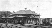
The C&O’s first 50 GP38’s were built by EMD in November and December of 1967. These 2000 HP units were numbered 3850-3899. These units were early GP38’s without paper air filters (the C&O also later purchased 10 GP38’s, numbered 4820-4829, with factory-installed paper air filters). The 3850-3899 carried 3600 gallons of fuel oil and 72 cubic feet of sand. They came painted in the plainest of the C&O’s paint schemes: Enchantment Blue overall with Federal Yellow frame stripes and minimal lettering. I chose to model number 3877, as I had a photo of that unit (available online at George Elwood’s site) in May of 1969.
If you want a GP38 in HO scale, there are two ways to go. One is to start with the Athearn GP38-2 and backdate it. This may be the way to go if you want one of the 4820-series units as the air filters are part of the model. The other way is to start with the ConCor GP38. I already had an undecorated ConCor model on hand, and I wanted a 3850-series unit, so I started with that. The ConCor model dates to the 1970’s when it was marketed by Atlas. For the time, it was state-of-the-art. The tooling on the shell was quite good and the mechanism very smooth. There are a number of problems with this model, though. Really big problems. First, while the mechanism runs quite well, the fuel tank is a big, ugly, angular thing that doesn’t much resemble any EMD fuel tank I’ve ever seen. Second, the powers-that-be at Atlas back in the 70’s insisted that the model have a one piece shell. That requirement precluded cab steps that were actual steps. On the model, the cab steps look more like playground slides (see Figures 1 and 2). Also, the model has a large (signal?) box cast into the right side of the short hood and some other box on the left rear cab wall. Neither appeared on the C&O prototype. Here’s what I did to correct those problems.
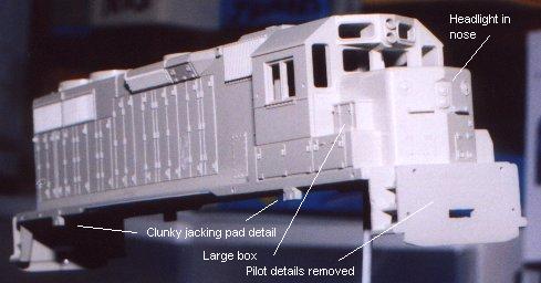
Figure 1. The right side of the ConCor shell before modification. Note the large box on the side of the short hood. Also, the sidesill is very thin where it passes over the fuel tank area. Pilot details have already been removed.
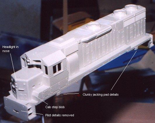
Figure 2. The left side of the unmodified shell. Note cab step “slide” and how it covers part of the hand brake.
| Part | Description | Part | Description |
| ConCor 152002* | EMD GP38 | Aline 29200 | Windshield wipers |
| Athearn 4626 | EMD GP50 (for the mechanism) | Aline 29210 | Cab sunshades |
| Athearn 42009 | Blomberg Truck Sideframes | Aline 29100 | Grab irons, drop type |
| Cannon 1008 | EMD hood unit doors | Detail Associates 3101 | Fuel gauge |
| Cannon 1201 | EMD 35 line & 40 series cab sub-base | Detail Associates 2402 | Exhaust stack |
| Cannon 1103 | 81" low short hood kit | Detail Associates 3203 | Air reservoir |
| Cannon 1501 | Cab kit | Detail Associates 1508 | MU Hoses |
| Details West 166 | Fuel filler | Detail Associates 2312 | Cab wind deflectors |
| Details West 139 | Air filter set | Detail Associates 3102 | Fuel tank fittings |
| Details West 157 | Fire cracker antenna | Detail Associates 1505 | MU Stands |
| Details West 192 | Pilot beam w/footboards | Detail Associates 2204 | Coupler lift bar w/bracket |
| Details West 190 | Leslie RSL-3L-R air horn | Detail Associates 1402 | Drop step |
| Precision Scale 3933 | Headlight | Smokey Valley | Handrail set for ConCor GP38 |
* This part number is for a BN decorated unit. The 1999 Walthers catalog doesn’t list an undecorated model.
Let’s begin with the frame and mechanism. Remove the Athearn GP50 shell and toss it in your parts box for some other project. Remove the motor and trucks and set them aside for now (but discard the metal strap that connects the trucks to the motor - we’ll replace it with wire). Using a cutting disk in a motor tool, remove the coupler mounting pads and the rudimentary fuel tank details. Be sure to use proper face protection during any use of a power tool. Next, we need to remove material from the frame to allow the ConCor shell to fit it. Use a grinding bit in your motor tool for that. Without further modification, the unit also sits about 6 scale inches too high above the rails, so you need to remove material to correct that as well. Refer to Figure 3 for the areas to thin - you want those areas to be about half their original thickness.

Figure 3. Changes to the Athearn frame.
Once you’ve got the shell fitting on the frame properly, you can add the fuel tank details. Refer again to Figure 3 and your prototype photos for the location of the fittings. I originally used the plastic fuel fillers from the DA set, but broke them both off during construction. The DW parts are metal and a little more durable. There’s also a very visible (drain ?) pipe on the left front of the fuel tank. I formed it from some heavy wire left from an old Gloor Craft caboose kit. I painted the frame with grimy black and dry-brushed rust spots on the edges of the tank using Floquil Roof Brown. I also painted fuel spills using a fine brush and flat black paint. I softened the edges of these spills slightly using black chalk dust and fixed it with an over coat of Testor’s Dullcote. Set the frame aside for now.
Turn your attention to the trucks. Disassemble them and clean the parts in warm, soapy water. Rinse them well and let them dry. Check the gears for flash or burrs and carefully remove any you find. Reassemble the trucks using the NWSL wheels. Paint the shiny metal sides of the trucks with flat black and the wheels (excepting the treads) with a dirty, rusty brown (I used a mix of approximately equal parts Floquil Rail Brown and Rust).
Assemble the Blomberg side frames. I added the speed recorder to the front journal of the left front truck. Add brake lines formed from .012 brass wire. I painted the side frames grimy black and dry-brushed them with the dirty, rusty brown mix. When dry, install the side frames on the trucks.
I used a wire wheel in my motor tool to clean and polish the surface of the bolsters where the trucks make contact. I used a small piece of electric tape to isolate the motor from the frame. I then reinstalled the trucks and motor. I wired in a DCC decoder using white LED’s for the headlights. This completes the frame and mechanism.
Start the shell modifications by removing unwanted detail (other than the cab and long hood end). I shaved off all the detail on the pilots, the lift rings, and the curved grab around the rear fan on the roof. I also removed the u-shaped “pockets” around the holes in the side sill for the hand rail stanchions. You’ve probably discovered by now that you also need to remove the backs of those holes as well to allow the shell to fit down on the frame. The jacking pads went too, along with the tall door on the right side of the long hood behind the cab (see Figure 4 - the door interferes with the new step). Finally, one of the exhaust stacks on my unit had the remains of a casting sprue in it. Rather than trying to dig it out without damaging the detail, I removed both stacks to make way for new parts.
I’d never used Cannon parts before this project, so I opted to start by replacing the long hood end. Follow the Cannon instructions for assembling the new end and removing the old end. My advice: cut off less of the old end than you think and file and sand the opening to its final size. Check the fit frequently. Then comes the tricky part: attaching the end to the shell. The ConCor shell is plastic, but it isn’t exactly styrene. I cemented the Cannon end in place with Testor’s liquid cement. When it was dry, I ran a bead of ACC along the entire joint. Let the whole thing cure for a couple of days before proceeding. Figure 4 shows the Cannon end in place.
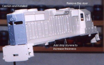
Figure 4. The ConCor shell with the Cannon long hood end in place. I’ve also pointed out a few more things to change.
The next step was the nerviest part for me: replacing the cab, short hood, and subbase with the Cannon parts. Assemble the cab, subbase, and short hood according to the Cannon instructions. The left side of the short hood and the front wall of the cab have vents for the cab heater - keep those. Once you have the new front end assembled, you’re ready to remove the old parts. Use a good quality razor saw and work carefully - measure twice and cut once. You’ll have to remove a little more of the long hood than you might like in order to get rid of the cab step “slide” on the right side and the box behind the cab on the left. I filed those areas to straight edges and filled the gaps with styrene (see Figure 5). You’ll also need to place a styrene patch on the left front to cover the gap where the front step “slide” used to be. Again, attach the styrene to the shell with Testor’s liquid cement and then reinforce the joint with ACC. When you’re satisfied with the fit of the cab to the shell, attach it with liquid cement and ACC. Let it cure for a few days before continuing work.
The last thing I did before starting the detailing was to increase the thickness of the thin part of the sidesills (see Figure 4). As best as I could tell, the sidesills on the model are about 3 scale inches too thin. I rounded up some very thin strip styrene and cemented and ACC’d it in place. Let these bonds set up really well before you go on.
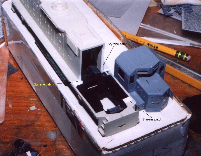
Figure 5. The assembled Cannon cab and the ConCor shell ready for cab installation.
I started the detailing with the pilots. The first step is to open up the holes for the coupler pockets to accept a new pocket with Kadee couplers. You could use a Kadee number 5 box, but I wanted something that looked like the massive pockets I saw in the photos. I followed the design of a pocket from a Front Range (now Trains Unlimited) GP9. See Figure 6 for the details.
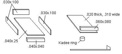
Figure 6. Details of the coupler pocket construction.
Start the pocket by cutting a piece of .040x.25 styrene strip to match the inside length of a Kadee #5 box. This is the bottom of your new pocket. Mark the location of the hole. Now, cut two pieces of .030x.100 styrene to match the length of the bottom. Glue these to each side of the bottom. Now cut a piece of .030x.100 to match the width of the bottom assembly and glue it in place. Make sure the sides are square with the bottom and let the whole assembly dry. Drill a hole to clear a #2-56 screw at the location you marked. Finally, cement a piece of .040x.040 styrene .310" long to the bottom of the pocket and flush with the front edge. This completes the bottom of the pocket.
The top is formed from a piece of .020 styrene .310" wide. The length is slightly longer than the bottom. Cement a piece of .060x.080 styrene to the top edge of the top and flush with the front edge. When it is dry, sand the front of the pocket to an angle (refer to Figure 6 and prototype photos). Then sand the front to a gentle arc that approximates the swing of the rear of the coupler. Fit the top and bottom together and mark the location of the hole in the top. Drill it out to clear a #2-56 screw. I had some old Kadee parts in the parts box; one of the sprues contained small rings that match the ones inside the number 5 box. I glued one around the hole in the top. Your pocket is now complete.
Now you can size the holes in the pilots to fit the new pockets. To mount the couplers, I cemented and ACC’d some ¼" styrene angle behind the holes in the pilots. Slip the coupler pocket in place and mark the location of the hole. Remove the pocket and drill and tap the mounting pad for a #2-56 screw.
Drill holes for the new footboards, MU hoses, coupler cut bar brackets, and the pilot grab iron. I attached the footboards and cut bars now, but left the MU hoses and the grabs off until after painting. I fashioned new anticlimbers out of scrap styrene following photos and an old Athearn shell. I attached them with ACC. Add the drop steps and MU stands. That completes the pilots - for now.
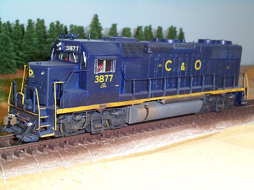
Figure 7. The front of the completed model.
After finishing the pilots, I worked my way up and over the shell. See Figures 7 and 8 for the location of the details. I installed the grabs in the short hood. Next came the Precision Scale headlight on the cab front. The horn and firecracker antenna were added to the cab roof. The bell is located on the fireman’s side of the long hood, just in front of the dynamic brake blister. I then added lift rings and the new exhaust stacks to the top of the long hood. I formed a new curved grab iron from .012 brass wire and located it behind the last fan on the long hood. If you haven’t already, drill out the rear headlight housing to accept the headlight bulbs. Finally, I ACC’d the grabs on the end of the long hood.
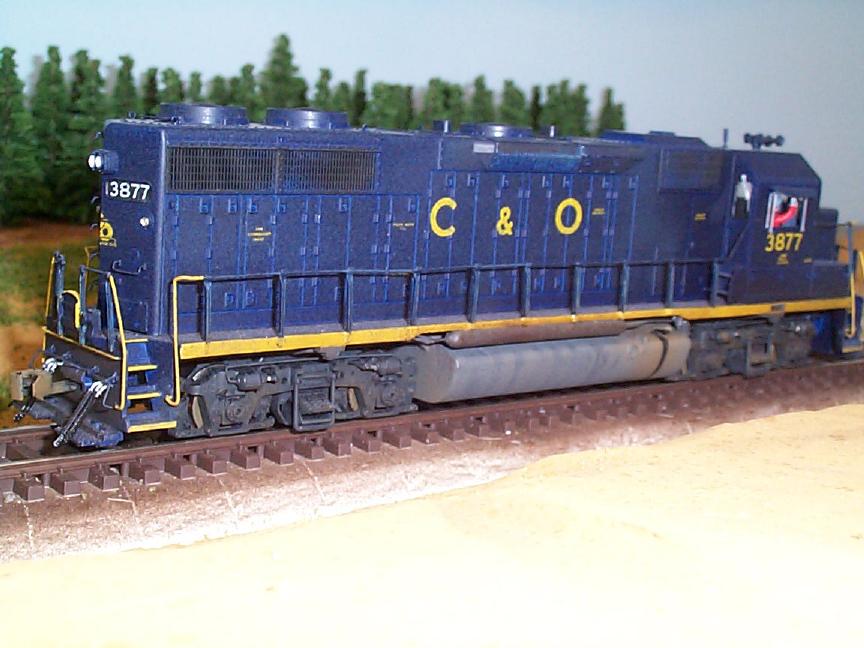
Figure 8. The rear of the completed model.
The painting on this model is fairly simple - load up your airbrush with Enchantment Blue and have at it. I used an old bottle of Accuflex I had around. Let the model dry really well. To paint the sidesills I used Testors Model Masters Signal Yellow. The decals came from Microscale and were applied following Microscale’s instructions. When they were dry, I hit the model with a coat of Testors Dullcote. Now, install the handrails and paint them blue, with yellow at the corner steps. Add the pilot grabs and MU hoses now, too. The grabs should be yellow. The MU hoses are Testors rubber with flat aluminum fittings.
The 3877 wasn’t too beat up in the photo I used, so I went easy on the weathering. I shot a very light mist of Pollyscale Enchanment Blue (which is just a bit lighter than the Accuflex) over the roof to simulate fading. I sprayed flat black over the fans and exhausts on the roof and on the grillwork on the sides. The lower part of the sides and the pilots got dusted with Milwaukee Road brown, which makes a nice old rust color. When the weathering is dry, seal it with a coat of Dullcote.
Once all the paint is dry, add the glazing in the cab windows. Now install the windshield wipers and MV Products class light lenses. I made lenses for the headlights from clear 1/16" styrene rod. I cut a piece long enough to reach through the headlight casing and into the shell. I polished one end with successively finer grits of sandpaper, working carefully to shape the piece to the gently rounded profile of a headlight lens. I fastened them in place with small amounts of Micro Kristal Klear.
To complete assembly, I slipped the LED headlamps into position and help them in place with black electrical tape (almost as good as duct tape). I then slid the chassis into place. I don’t have a mounting system - only its own weight holds the shell in place. I mounted Kadee couplers in the coupler pockets and 3877 was ready to roll.
Menu |
You are visitor number
to this site since the new counter was inaugurated on June 28, 2004.
This site was originally established in 1997.
| Mail comments to: | Larry Z. Daily |
Please note that, due to a huge volume of spam coming in on my email account, I’ve had to change my email address. The new address is lzdaily@nospam.piedmontsub.com (but remove the nospam and the dot before piedmontsub.com).
Copyright © 1997-2024 Larry Z. Daily. All rights reserved.
All materials on this Web site are protected by United States
copyright law. This includes, but is not limited to, articles and graphics. Unless
otherwise indicated, these materials are the property of Larry Z. Daily and may not
be used without prior written permission of Larry Z. Daily
| The author strongly supports | Site edited with | Photos edited with | Maps created with | Tooltips created with BoxOver | The site counter is a product of |
|
|
|
|
|
|
|